As we all know, frequency converter has many protection functions, such as over-current, over-voltage, overload protection and so on. With the continuous improvement of industrial automation, frequency converter has been widely used. This article will show you how to use a multimeter to measure the quality of the inverter.
It should be noted that in order to ensure personal safety, the machine must be powered off, and the inverter input power lines R, s, t and output lines u, V, w must be removed before operation! First, set the multimeter to the "secondary pipe" position, and then test it by the red and black probes of the multimeter as follows:
The black probe contacts the negative pole P (+) of the DC bus, and the red probe contacts R, s and t successively, recording the displayed value on the multimeter. Then contact the red probe with n (-), and the black probe with R, s and T in turn, and record the display value of the multimeter. If the six display values are basically balanced, it indicates that there is no problem with the rectifier or soft start resistance of the converter diode, otherwise the rectifier module or soft start resistance at the corresponding position is damaged, phenomenon: no display.
The red probe contacts the negative pole P (+) of the DC bus, and the black probe contacts the U, V and W successively, recording the displayed value on the multimeter. Then contact the black probe with n (-), the red probe with u, V and W in turn, and record the display value of the multimeter. If the six display values are basically balanced, it indicates that there is no problem with the inverter IGBT module, otherwise, the IGBT inverter module at the corresponding position is damaged, phenomenon: no output or fault is reported.
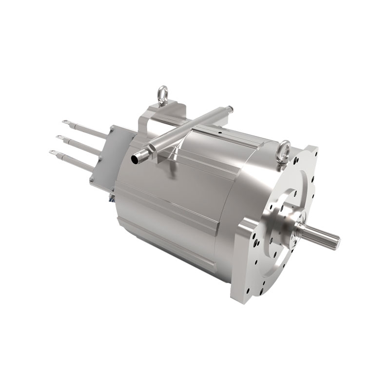
A power matching asynchronous motor is driven by a frequency converter to run without load, and the frequency f is adjusted, which starts to decrease from 50Hz to the lowest frequency.
In this process, the ammeter is used to detect the no-load current of the motor. If the no-load current is stable in the process of frequency reduction and can be kept basically unchanged, it is a good inverter.
The lowest frequency can be calculated in this way, (synchronous speed - rated speed) × pole logarithm P ÷ 60. For example, a 4-pole motor with a rated speed of 1470 rpm and a minimum frequency of (1500-1470) × 2 ÷ 60 = 1Hz.
There is no problem with the soft start resistor. On the contrary, the rectifier module or the soft start resistor at the corresponding position is damaged. Phenomenon: no display.
The red probe contacts the negative pole P (+) of the DC bus, and the black probe contacts the U, V and W successively, recording the displayed value on the multimeter. Then contact the black probe with n (-), the red probe with u, V and W in turn, and record the display value of the multimeter. If the six display values are basically balanced, it indicates that there is no problem in the inverter IGBT inverter module, otherwise, the IGBT inverter module at the corresponding position is damaged, phenomenon: no output or fault is reported.
A power matching asynchronous motor is driven by a frequency converter to run without load, and the frequency f is adjusted, which starts to drop from 50Hz to the lowest frequency.
In this process, the ammeter is used to detect the no-load current of the motor. If the no-load current is stable in the process of frequency reduction and can be kept basically unchanged, it is a good inverter.
The lowest frequency can be calculated in this way, (synchronous speed - rated speed) × pole logarithm P ÷ 60. For example, for a 4-pole motor, the rated speed is 1470 rpm, the lowest frequency = (1500-1470) × 2 ÷ 60 = 1Hz.
Identification of AC and DC solid-state relay: generally, beside the input and output ends of DC solid-state relay shell, there are "+" and "-" symbols, and the words "DC input" and "DC output" are marked. The AC solid-state relay can only mark "+" and "-" symbols on the input end, and the output end has no positive or negative difference.
Discrimination between input end and output end: solid state relay without identification, multimeter R × 10K gear, to distinguish input end and output end by measuring the positive and negative resistance values of each pin respectively. When the forward resistance of two pins is small and the reverse resistance is infinite, the two pins are the input and the other two pins are the output. In a small resistance measurement, the black lead is connected with a positive input and the red lead is connected with a negative input.
If the positive and negative resistances of both pins are 0, the solid-state relay is broken down. If the positive and negative resistance values of each pin of the solid-state relay are infinite, it means that the solid-state relay has been open circuit damaged.

|
|

|
| The public, | Mobile station |
 0755-81719517
|
|
 0755-81719530 0755-81719530 |
 [email protected] [email protected] |
 Floor 1, 5 and 6, building 7, lijincheng science and technology industrial park, gongye dong road, longhua new district, shenzhen Floor 1, 5 and 6, building 7, lijincheng science and technology industrial park, gongye dong road, longhua new district, shenzhen |
|

 English
 中文
中文